


ABL-DX Backdrop Lift System Instructions
How To Install ABL DX Backdrop Roller System
Click here to download the ABL-DX Lift System Instructions in .pdf format.
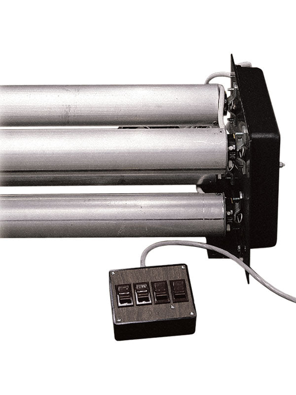
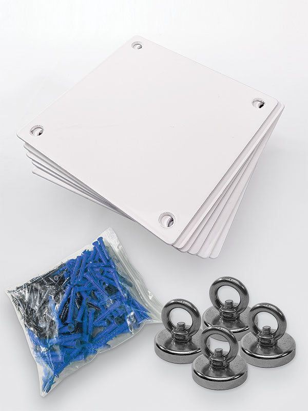
This photography background roller system has the motors pop-riveted into the tubes and it has mounting support plates at each end. The attachment brackets for these plates are shipped for ceiling mounting (A) but can be moved for attaching to the wall (D). Each roller unit has two mounting plates- one for the motor end mounting and one for the pillow block mounting (as shown in figure 1&2).
Single Roller ABL-DX System:
Uses ABLC individual mounting plates (not shown):
Mounting plate dimensions: 4.5" Wide (side B) x 3.75" High (Side C)
Two, Three, or Four Roller ABL-DX Systems:
Mounting plate dimensions:
15, 1/4" Wide (Side B) x 10, 5/8" High (Side C)
Five, Six, Seven, & Eight Roller ABL-DX Systems:
Mounting plate dimensions:
29.5" Wide (side B) x 10.75" High (side C)
2) The small brackets can also be removed to mark the surface for the bolt-holes for pre-drilling.
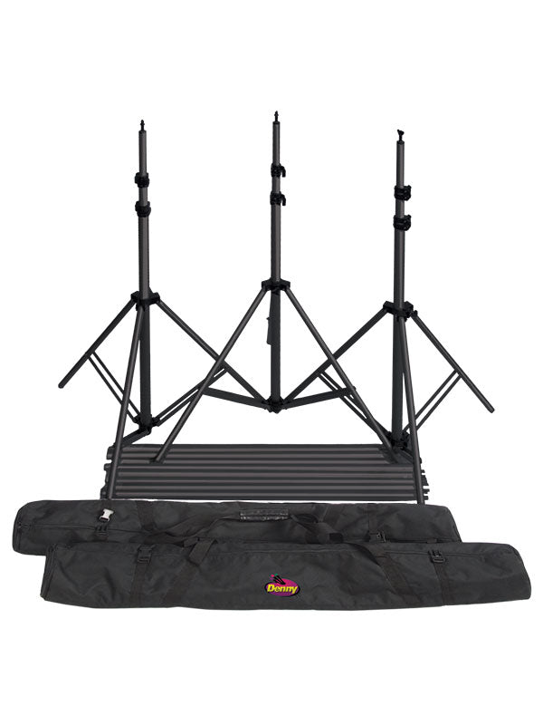
3) Mount the motor end assembly on the right side using 3 1/2’ or longer lag bolts or standard hex head bolts (not included) to the studs or beams.
4)Mount the bearing plate the same way in a parallel position to the motor end.
5)The distance between the two mounting plates will be 2 1/2" plus the roller size. (For example, on a 12’ system, the distance between the plates is 146 1/2")
6)Insert the roller end into the pillow block plate first, and then slide the motor drive end into the square holed bracket. Secure it with the provided cotter pin.
7)Plug the motor unit into the studio wall outlet. (NOTE: In referring to the right side, it is right side as you face it from the camera.)


Tips for Attaching Backdrops to Metal Rollers
1) Lay background on the floor with the painted side up. Place the roller on top at the top and curl the canvas around the roller with the drive end of the roller on the right side.
2) Attach the canvas with 3” strips of duct tape across the seam every 18” starting in the middle and proceeding towards each side making sure no puckers develop in the canvas. Next, again starting in the middle, pull two solid strips of duct tap towards each end.
3) Insert roller end to the left into the bearing mounting plate all the way. Then slide the opposite end to the right and onto the motor drive shaft, rotating roller to fit the slot on the shaft.
4) Insert the hitch pins all the way through the small holes in each roller end, passing through the notch in the motor slot and securing the roller outside the other plate.
White Button Controls Up
Yellow Button Controls Down


Limit Switch Adjustment
The ABL-DX motor has a built-in switch easily permits setting both the UP and DOWN limits (stopping points) of the motorized system. The Limit switch can be adjusted as follows:
1) Ensure all switches are in OFF position on the control box.
2) Remove yellow protective cap from the head of the motor.
3) DEPRESS FULLY both motor limit switch buttons (white and yellow). They will automatically lock in the down position. Now, operate control box switches to ensure system operates correctly.
4) Identify the Up motor limit switch- push the button WHITE. Press control box switch to the up direction until the desired position is reached. Return switch box switch to the OFF position.
5) Unlock the UP motor limit switch button by depressing and releasing.
6) Repeat steps 4 & 5 until all the control box switches have been set for the UP limits.
7) Identify the Up motor limit switch- push the button YELLOW. Press the switch on the control box to the down direction until the desired position is reached. Next, return switch on the switch box to the OFF position.
8) Unlock the down motor limit switch by depressing and releasing it.
9) Repeat steps 7 & 8 until all control box switches have been set for DOWN limits.
10) Replace yellow motor protective cap.
For continuous running such as seamless paper backgrounds, depress BOTH buttons & yellow) at the same time and system will travel continuously in both directions.
YOUR DENNY ROLLER SYSTEM SHOULD NOW BE READY TO OPERATE.